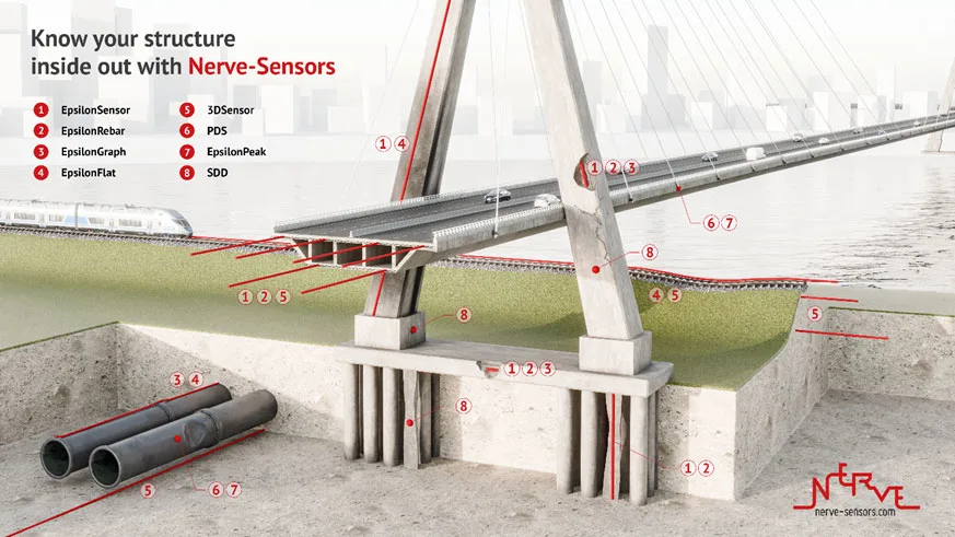
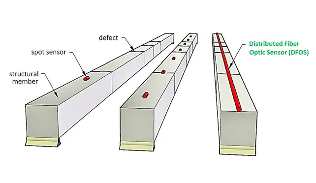
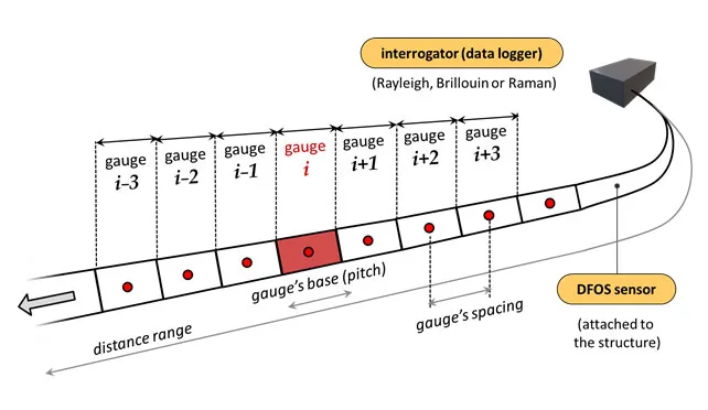
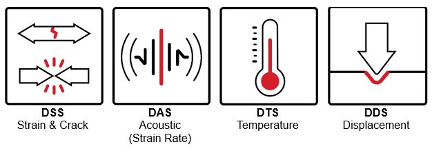
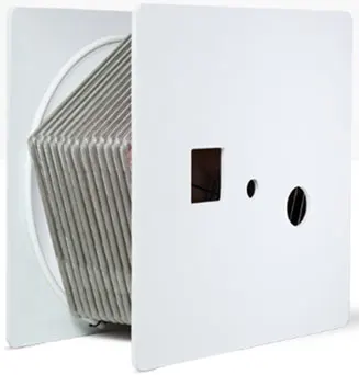
Distributed Fibre Optic Sensing (DFOS) Technology
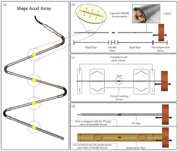
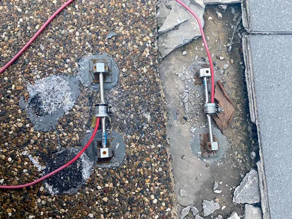
Measurand’s Shape Accel Array (SAA)
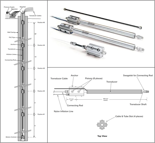
Modified Multiple Point Retrievable Extensometer (Geokon Model A-9)
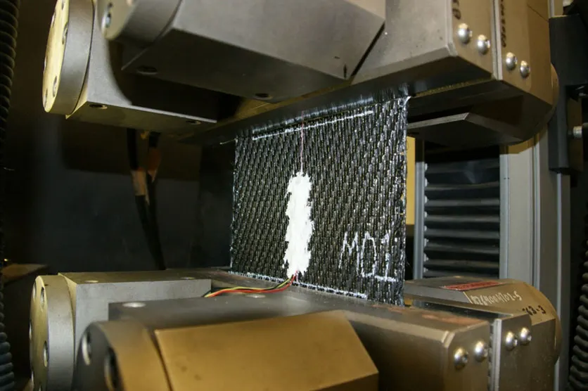
Unique Strain Gauges on Geosynthetics Materials
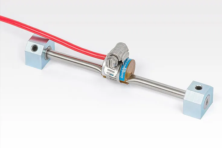

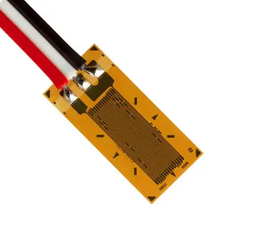
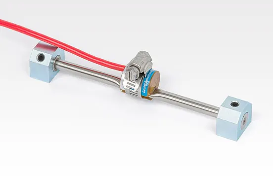
Strain Measurement - VW & Resistance Strain Gauges
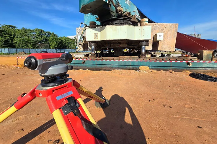
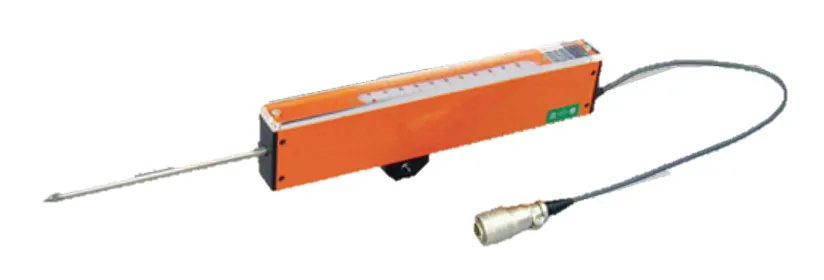
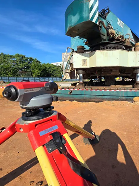
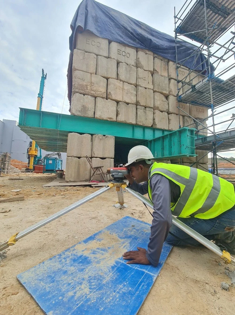
Displacement Measurements - LVDT, settlement marker, survey method via total station & dumpy level
Inclination – Inclinometer

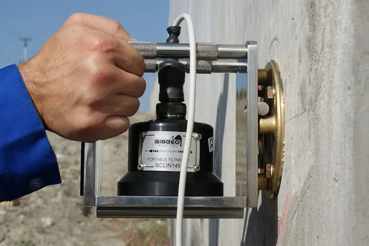
Building Tilting Measurement - Tiltmeter

Water Level & Pore-water Pressure Monitoring (Piezometer)

Noise & Vibration Monitoring
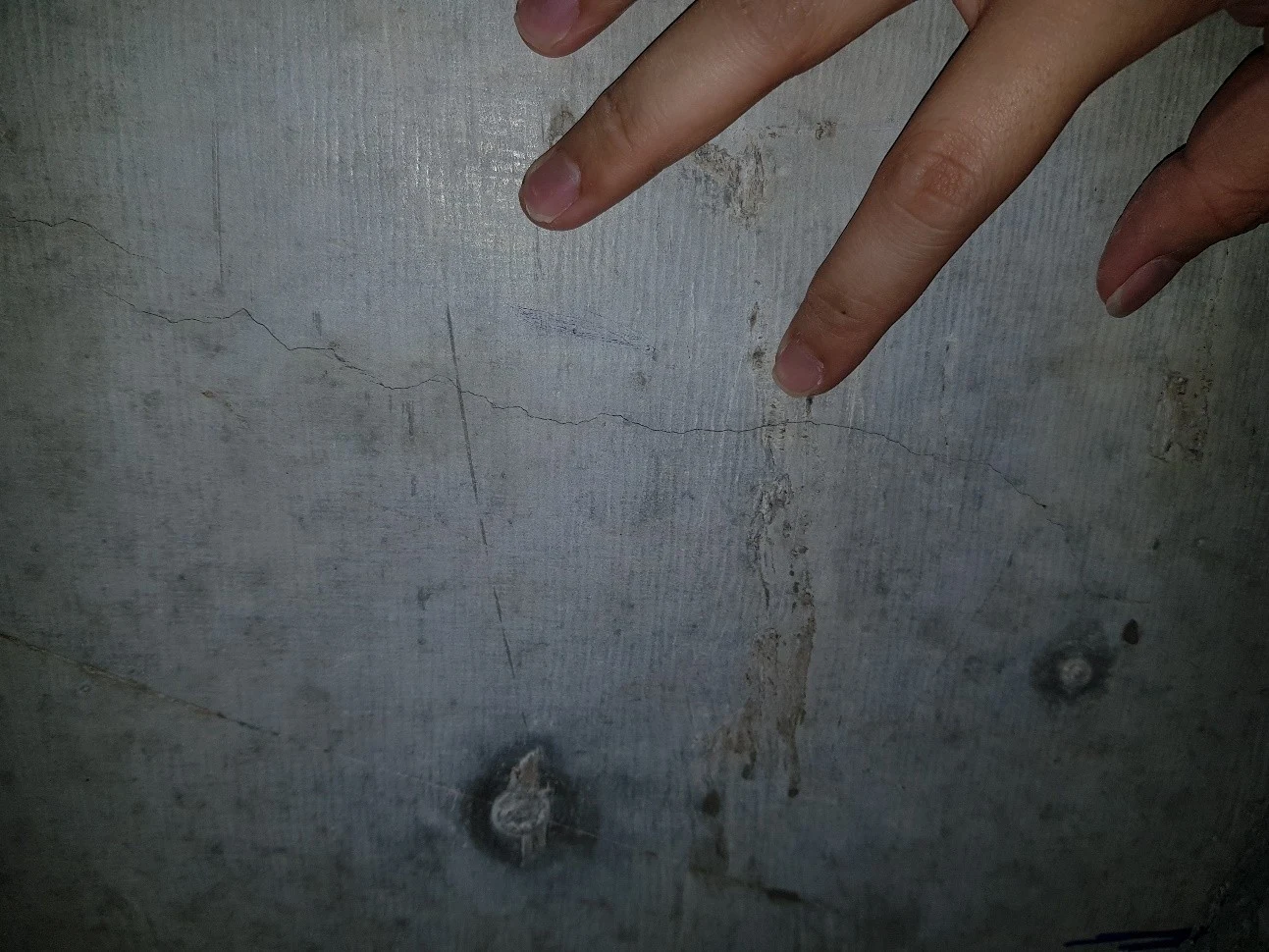
Dilapidation Survey
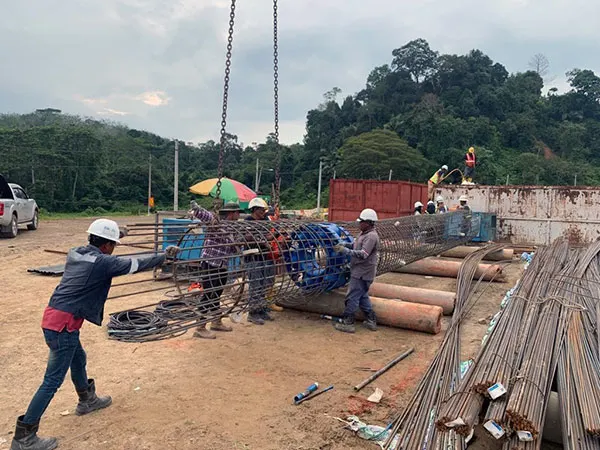
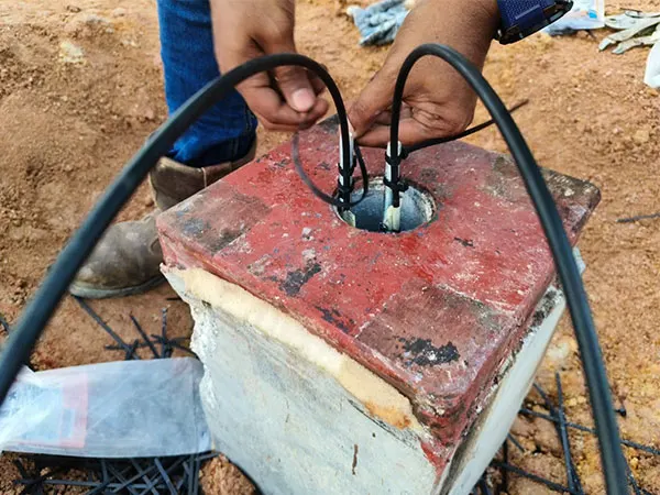
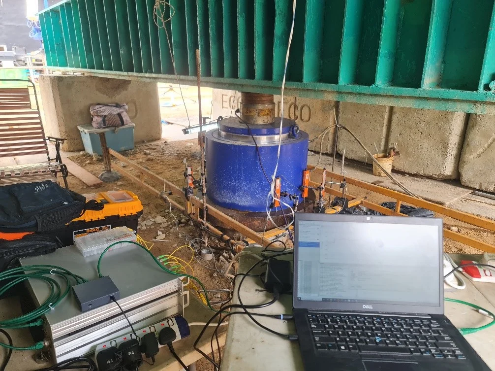
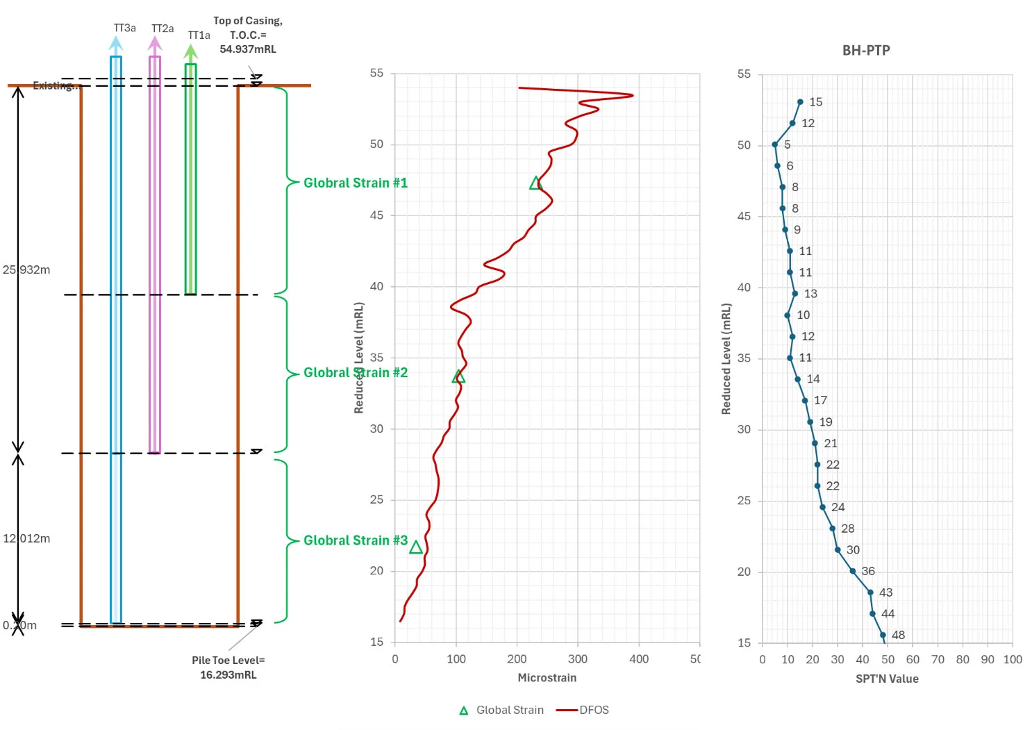
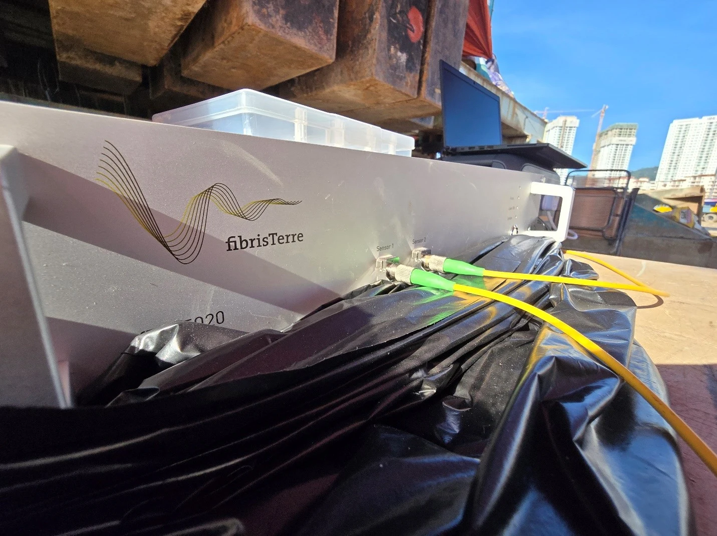
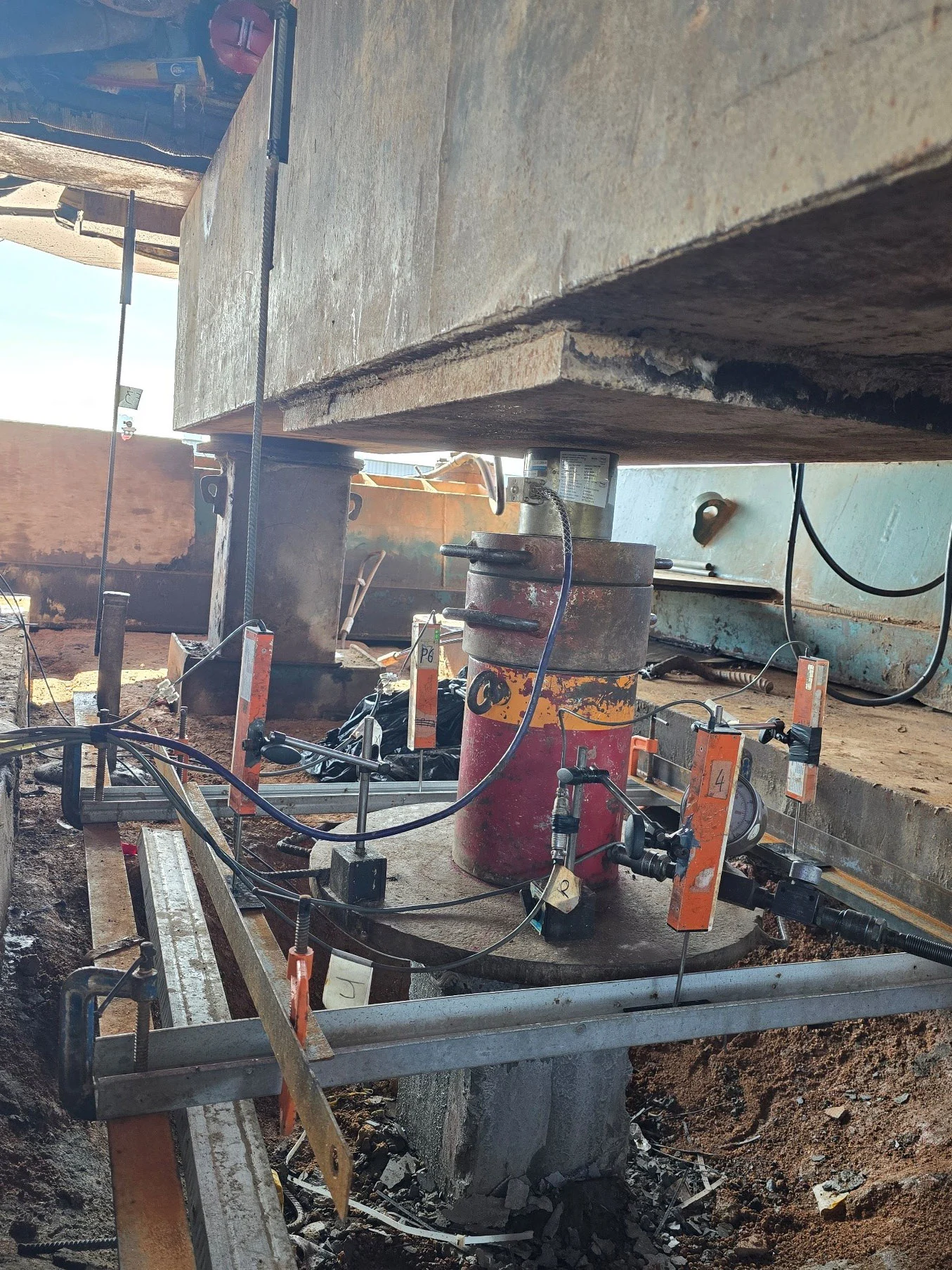
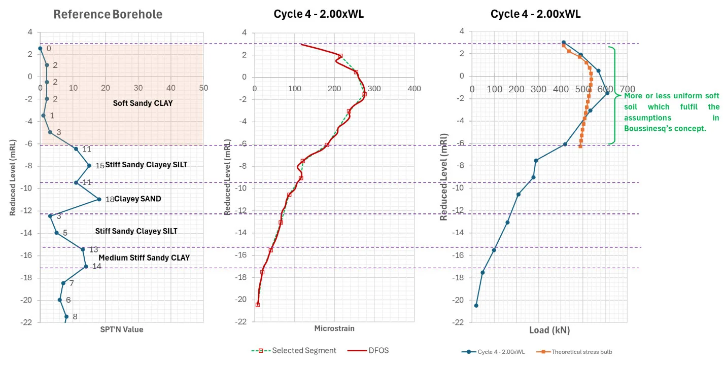
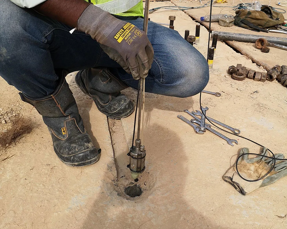
DFOS Instrumented Bored Pile in a Static Load Test
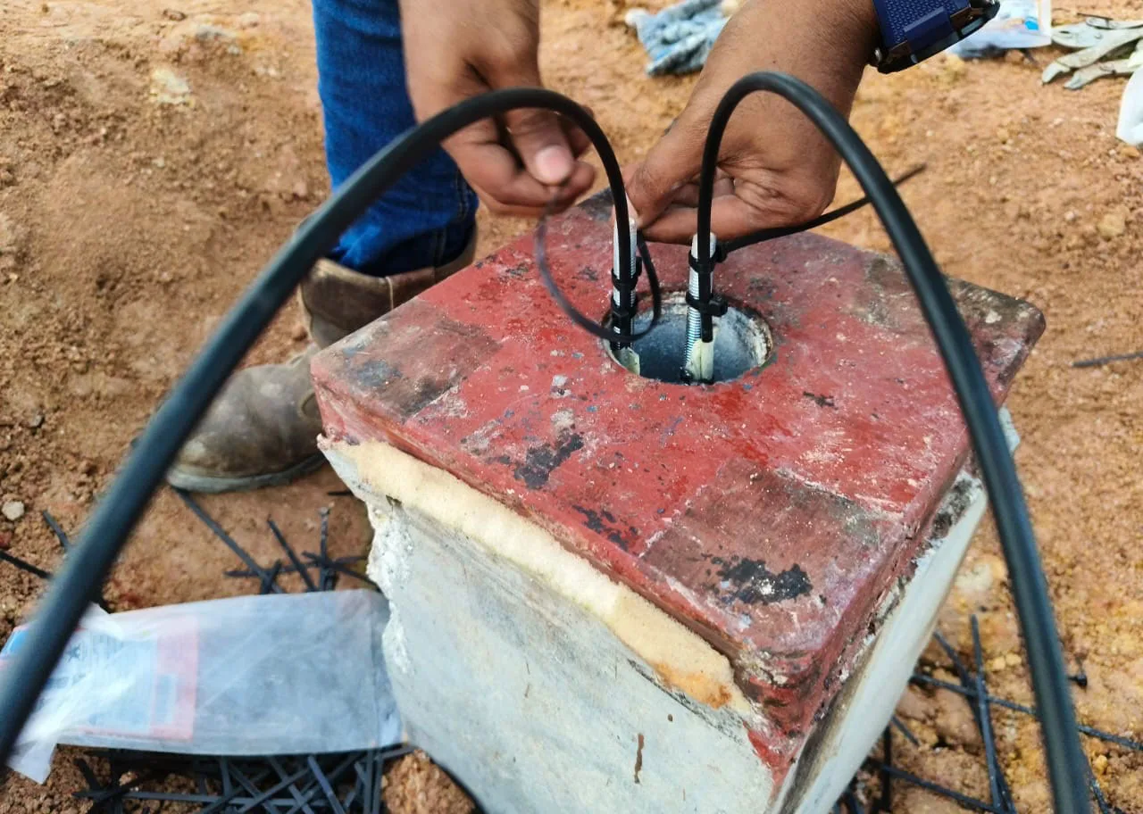
DFOS Instrumented Driven Concrete Pile in a Static Load Test
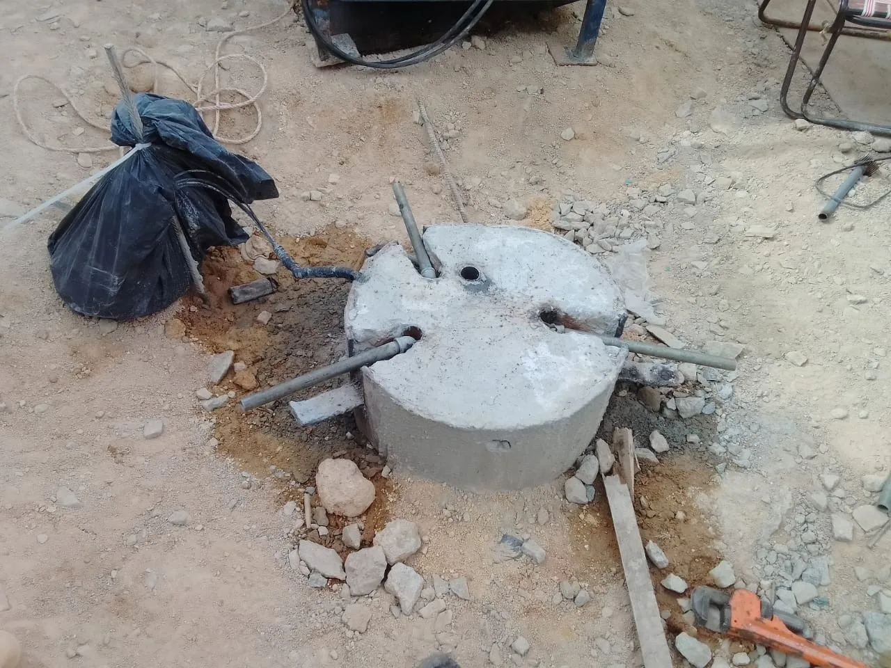
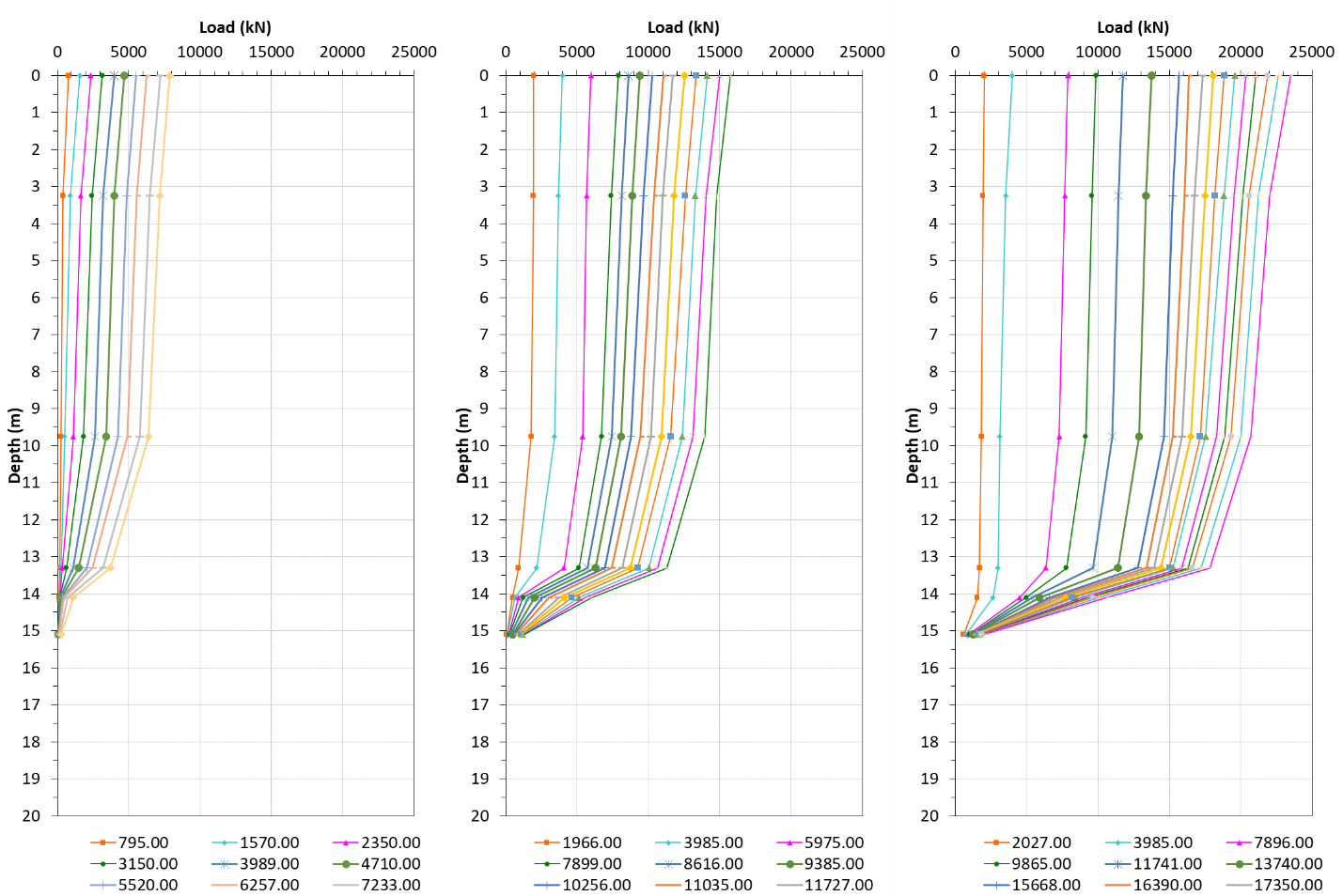
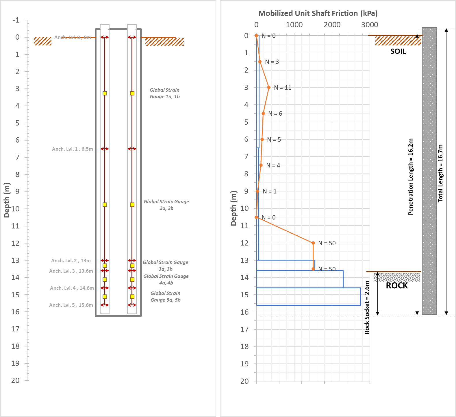
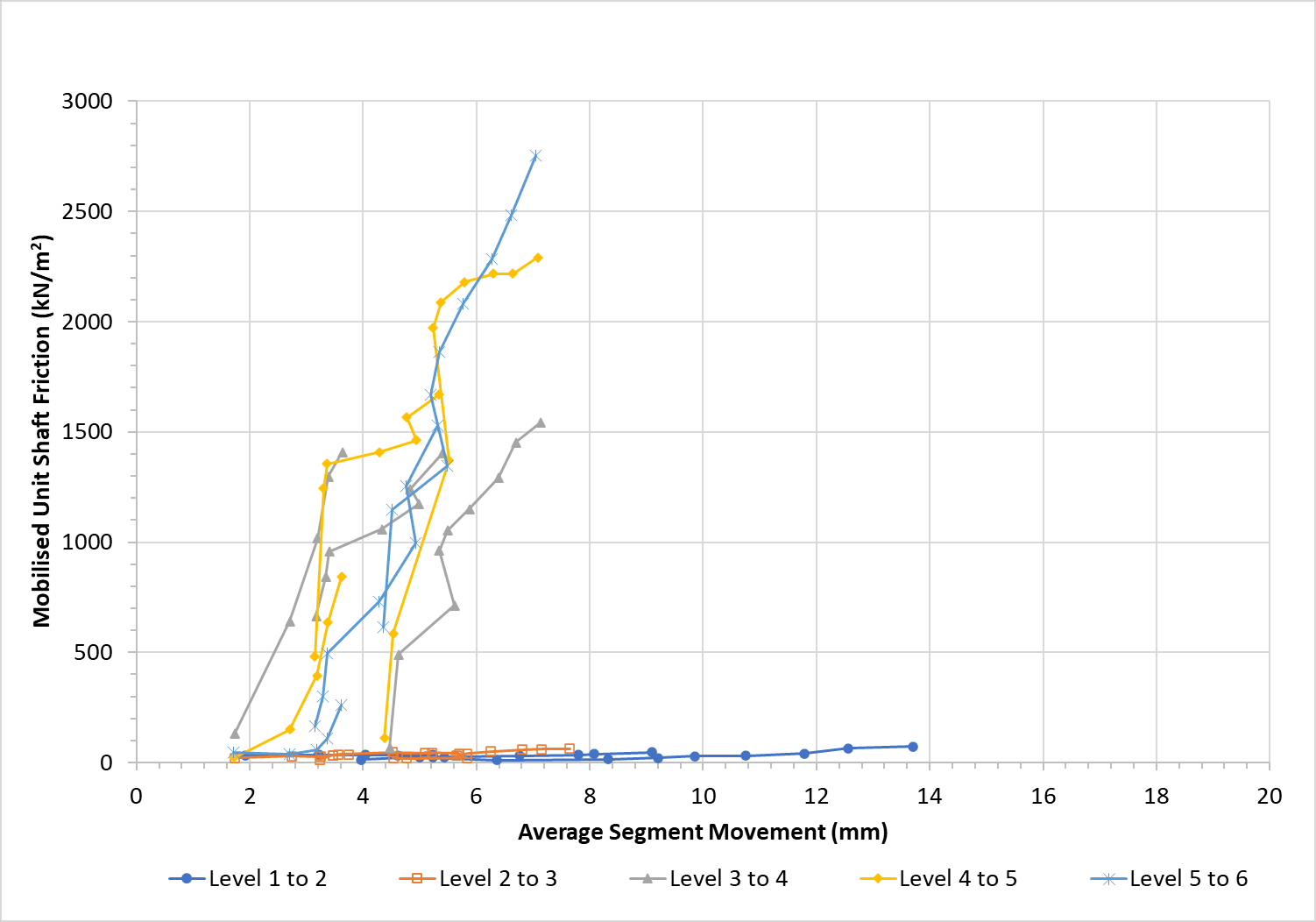
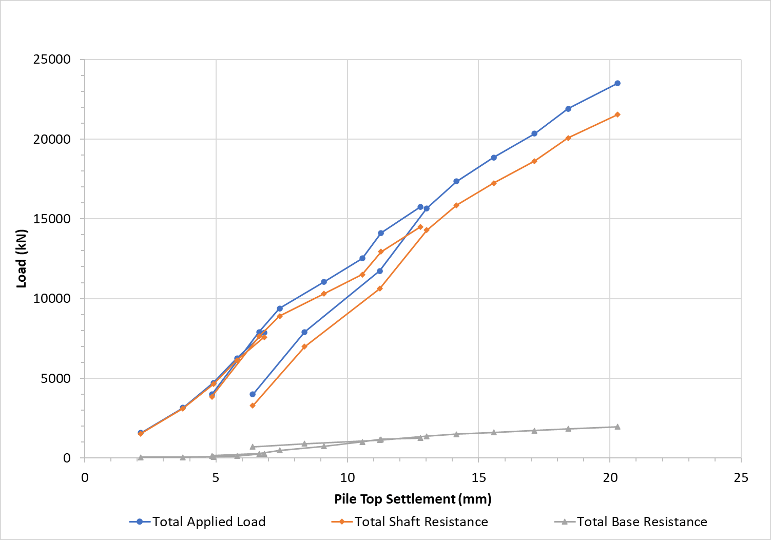
A Maintained Load Test on an Extensometer A-9 Instrumented Bored Pile
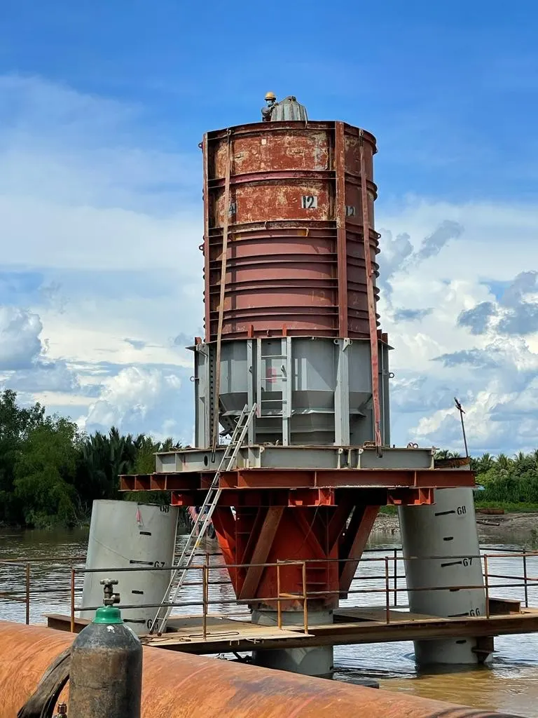
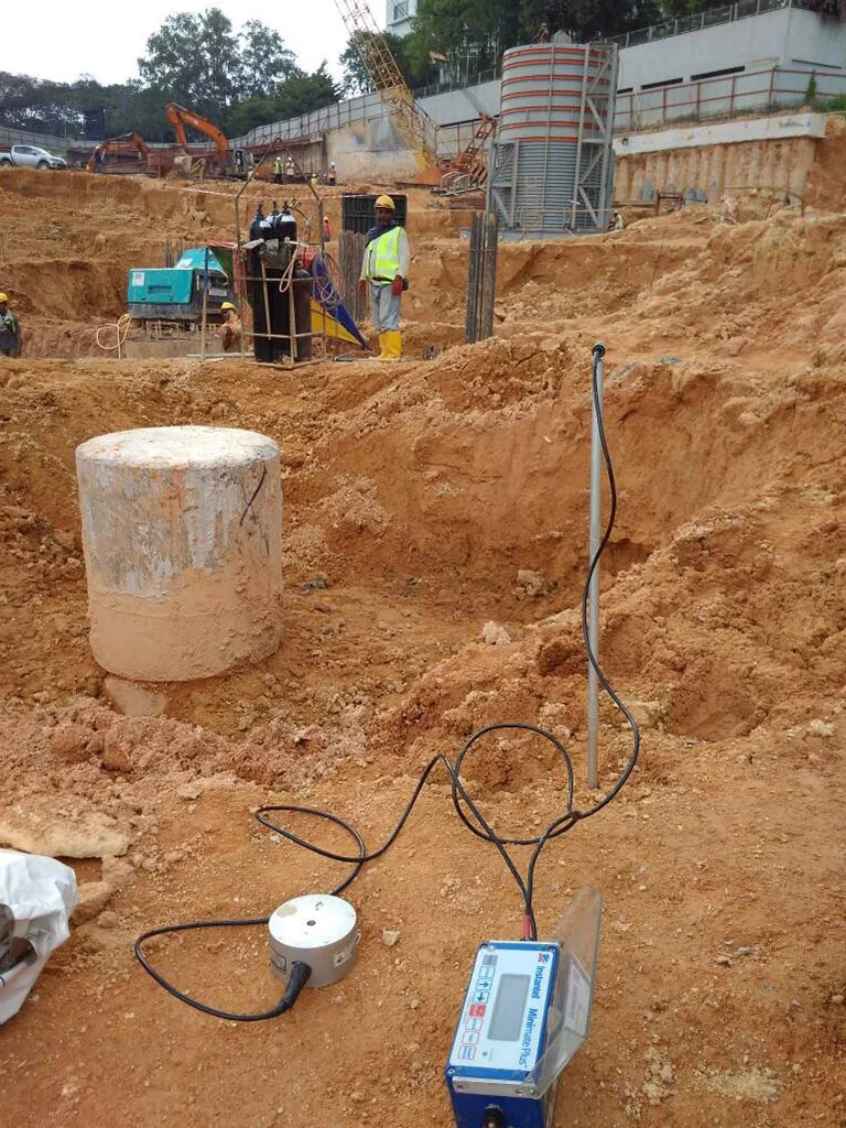
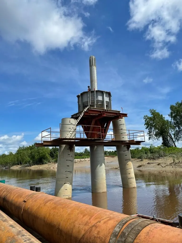
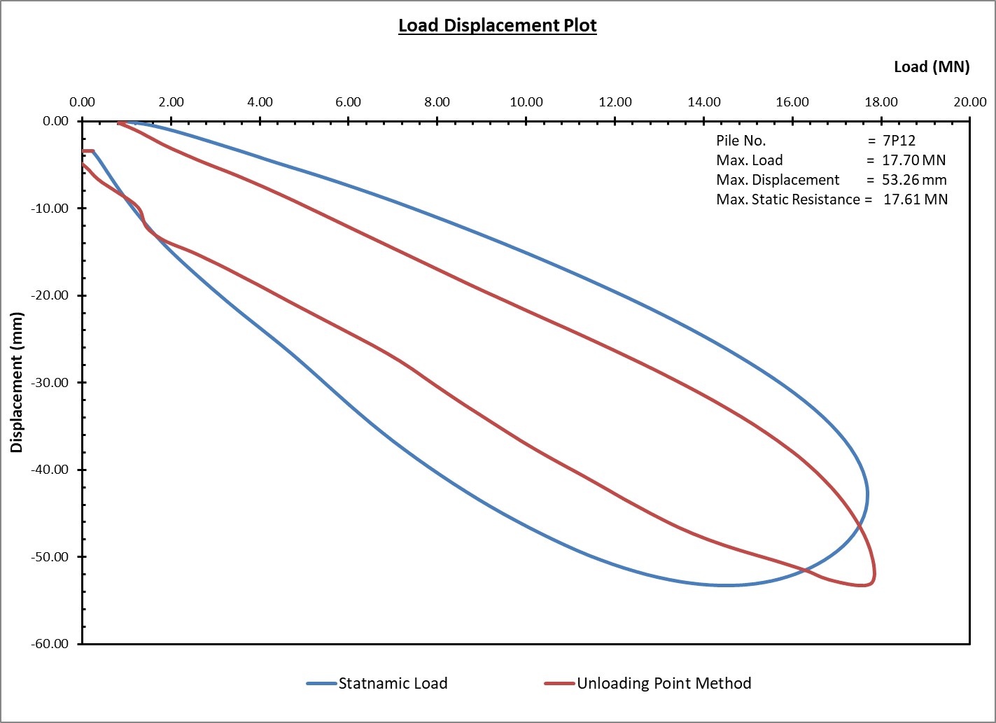
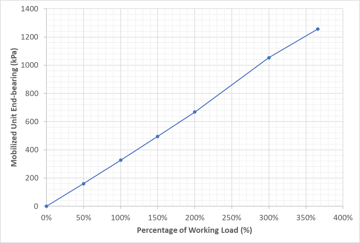
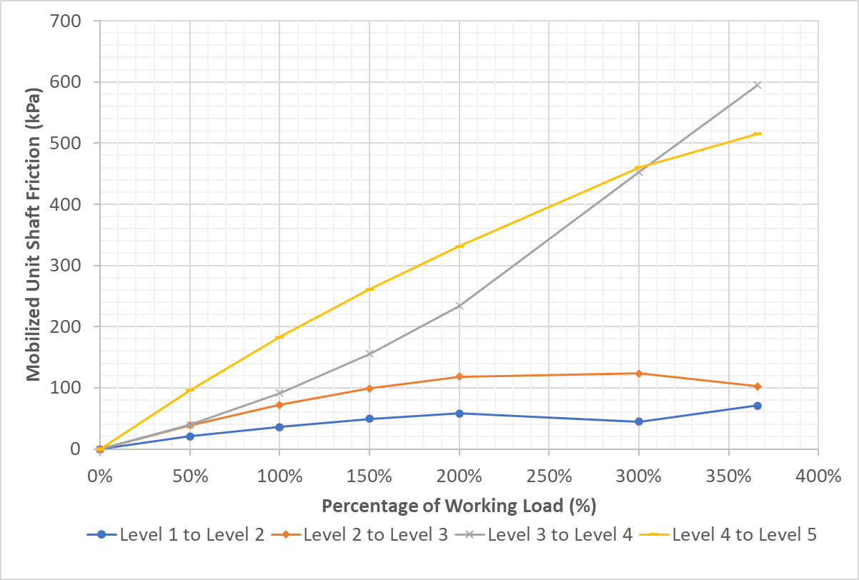
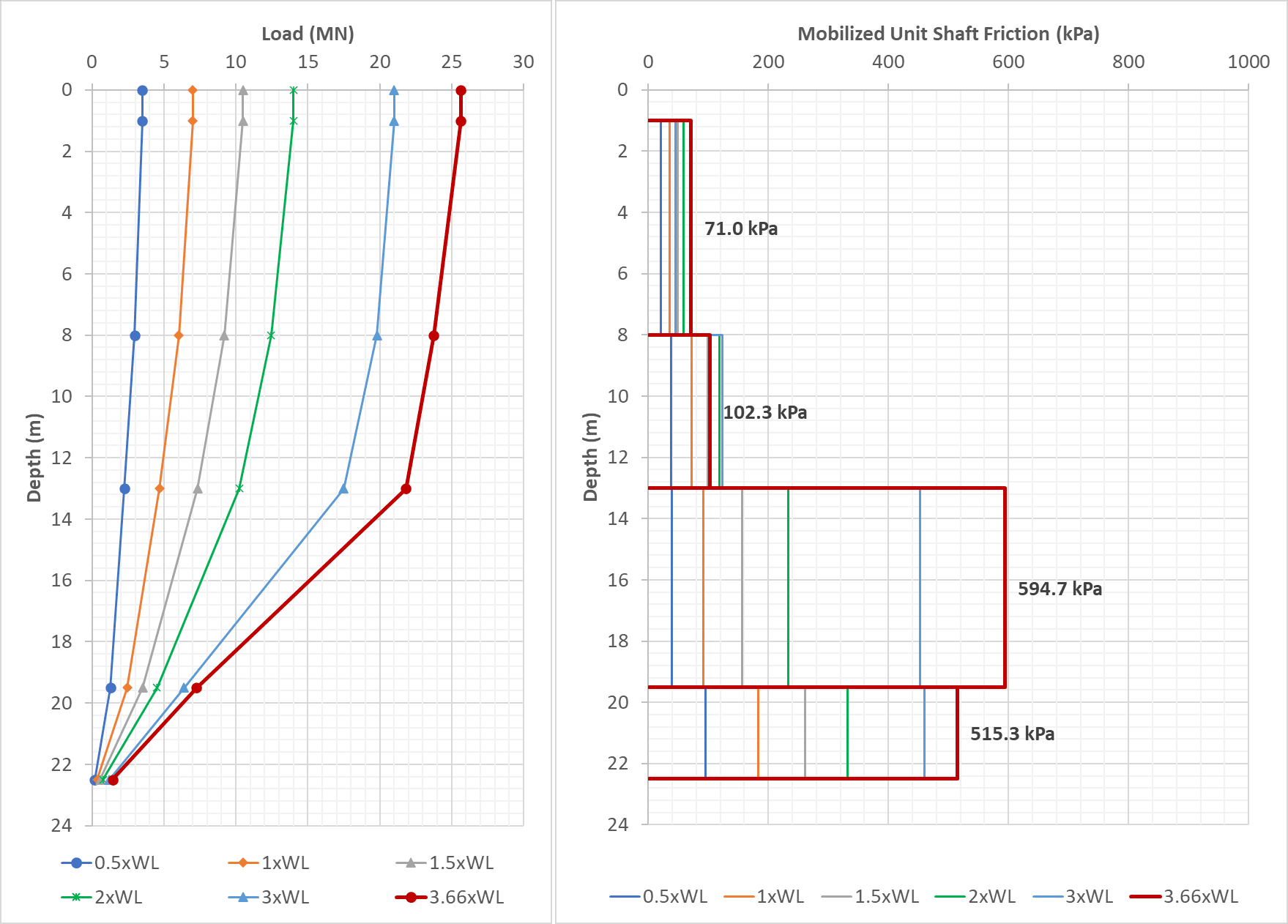
A Resistance-type Strain Gauges Instrumented Marine Bored Pile in a Statnamic Load Test
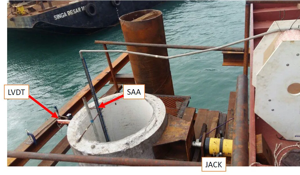
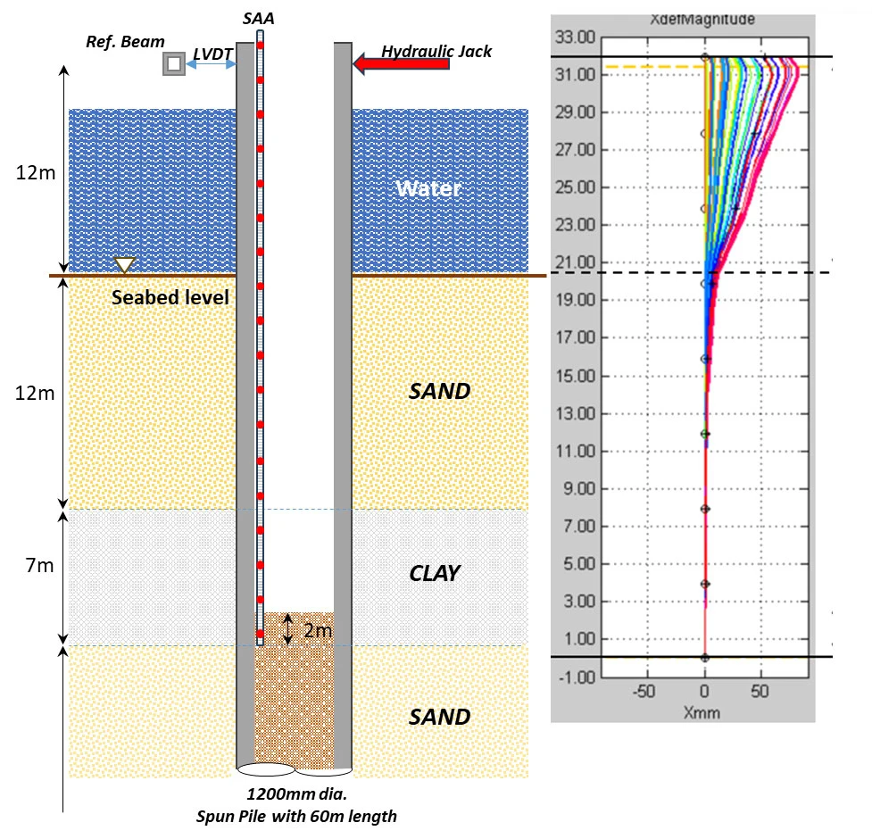
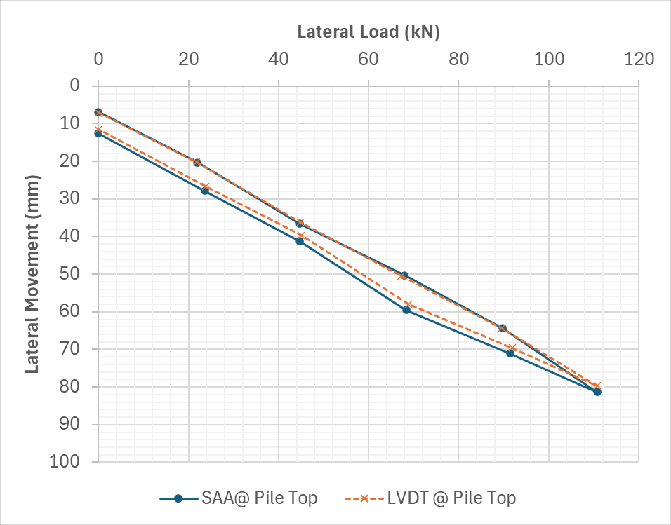
Lateral Pile Load Test on a Spun Pile
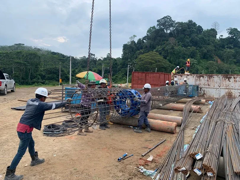
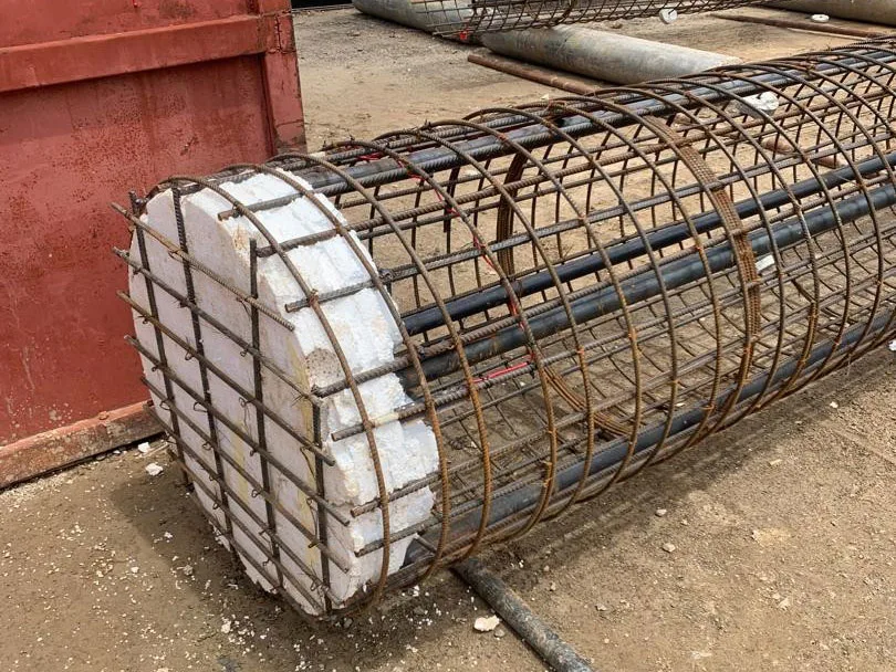
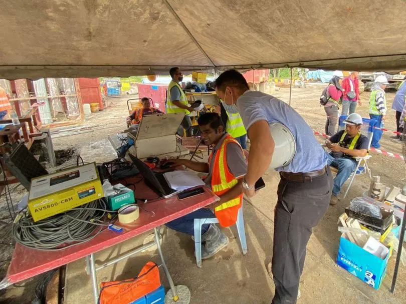
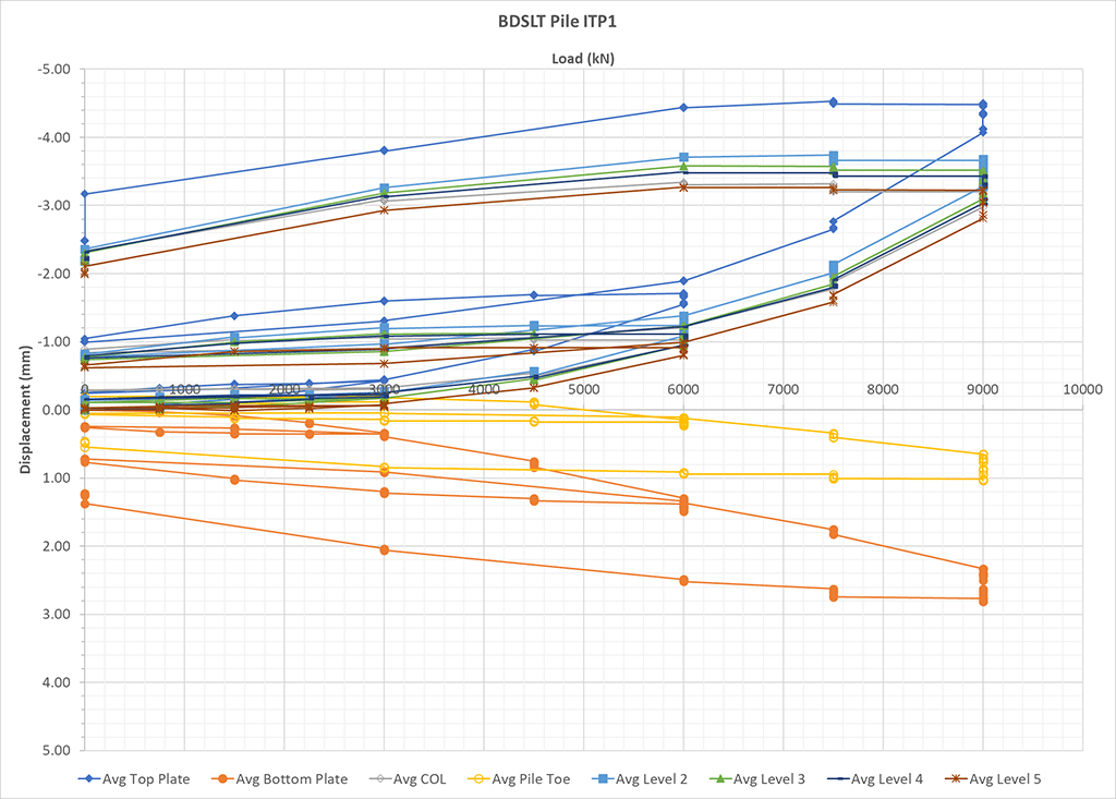
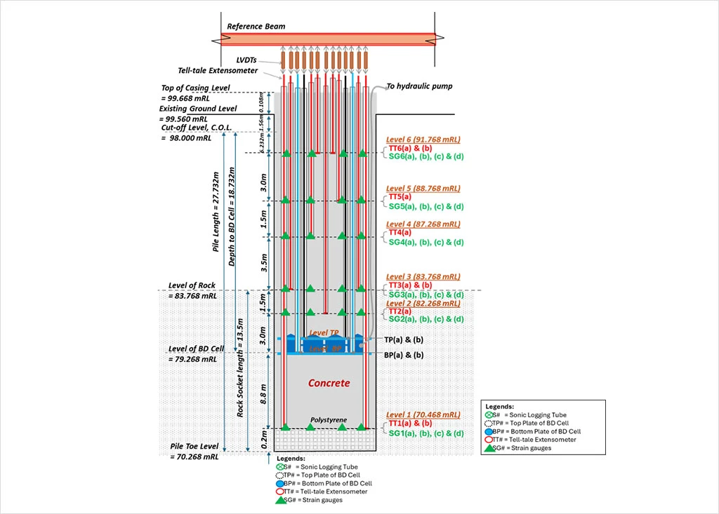
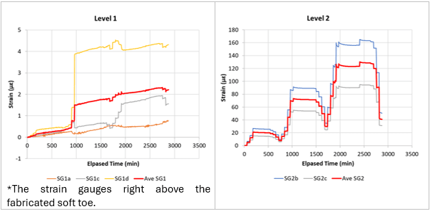
A Prefabricated "Soft Toe" in an Instrumented Bidirectional Static Load Test
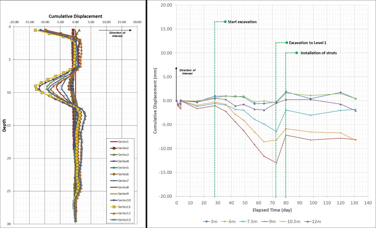
Inclinometer Measurement of Retaining Structure in Deep Excavation
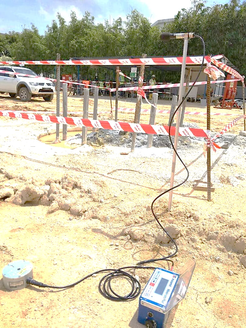
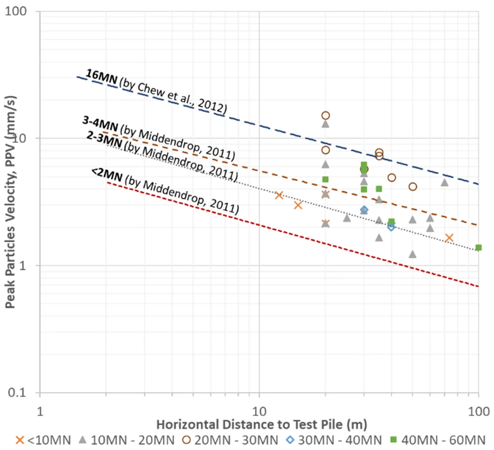
Vibration Monitoring for Statnamic Load Tests
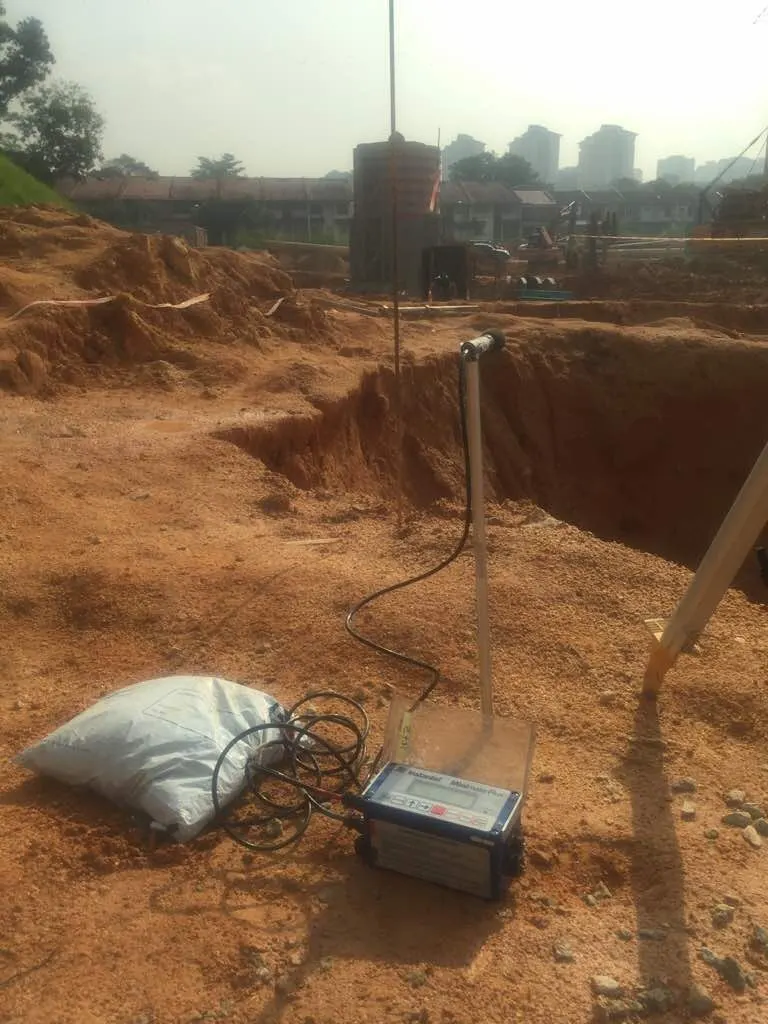
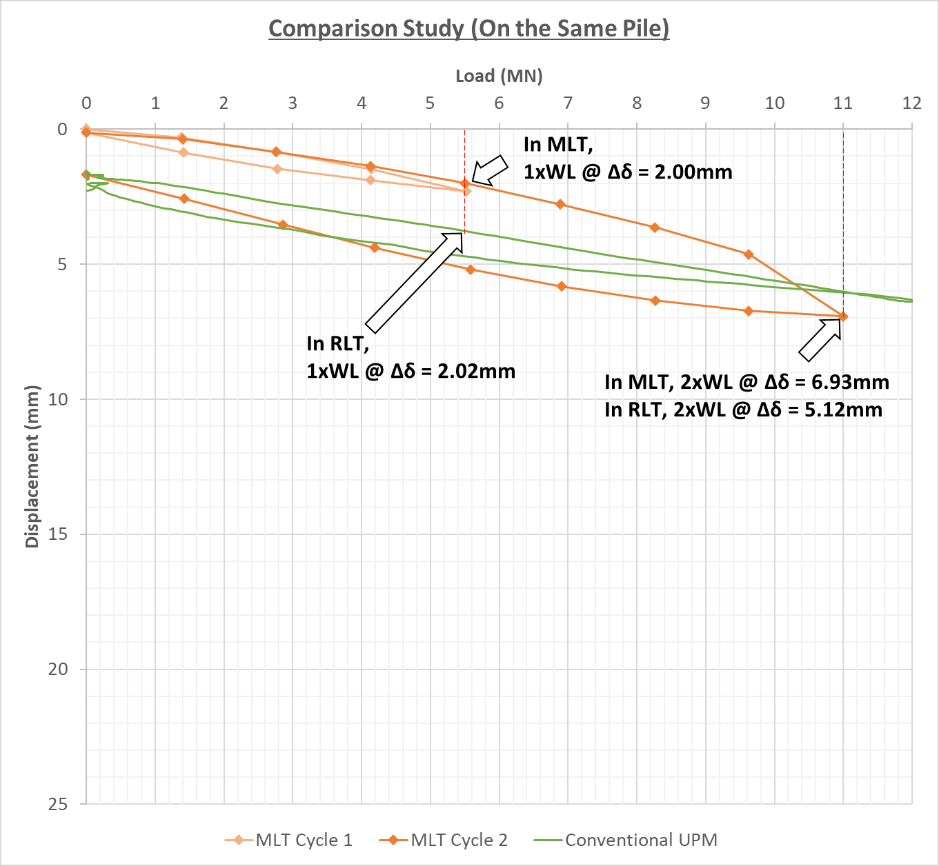
A Comparison of Statnamic Load Test and Conventional Maintained Load Test


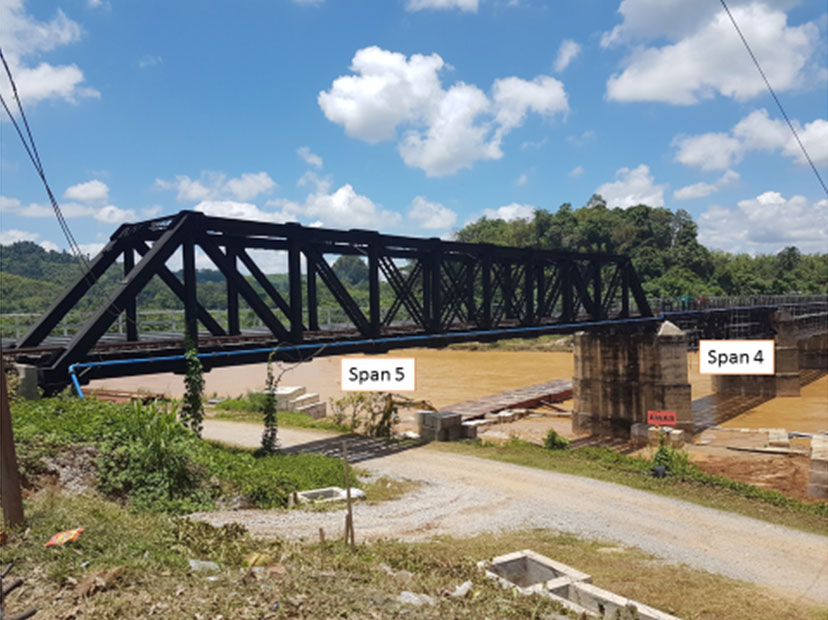
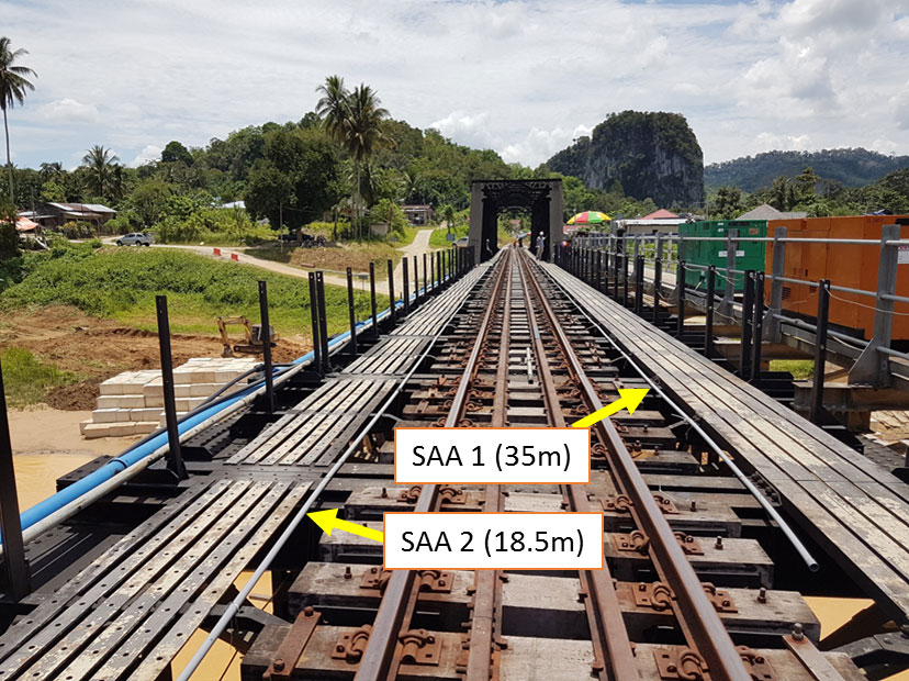
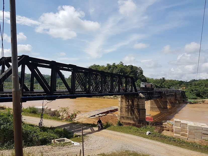
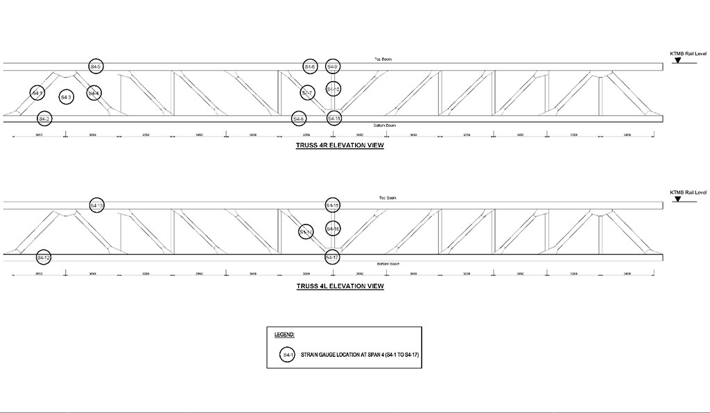
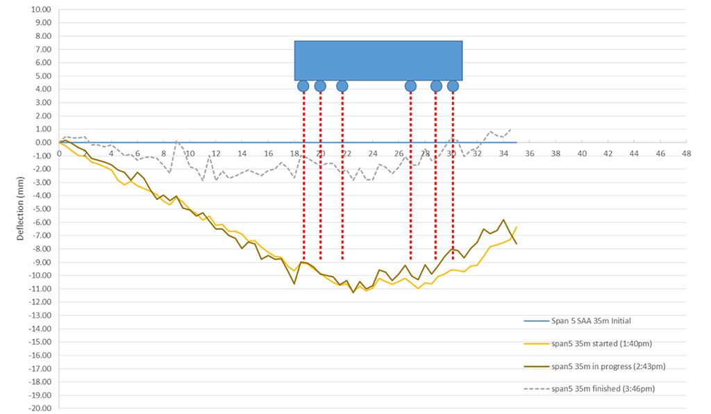
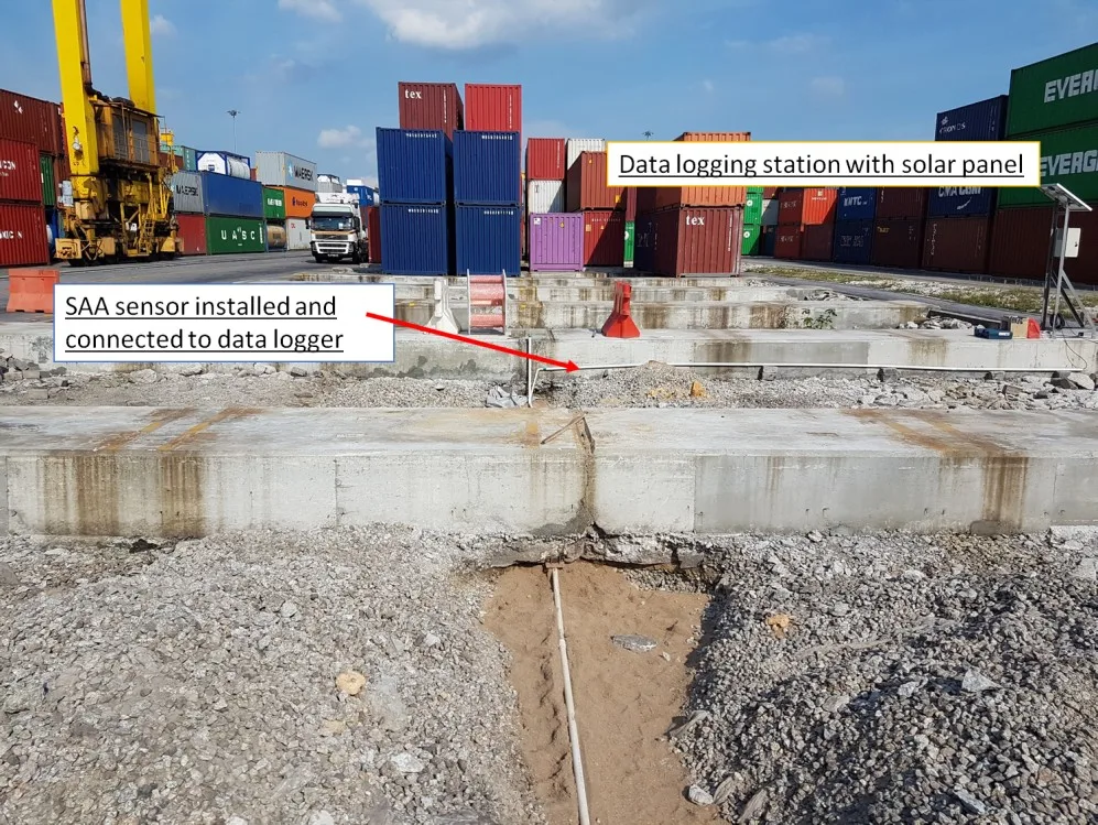
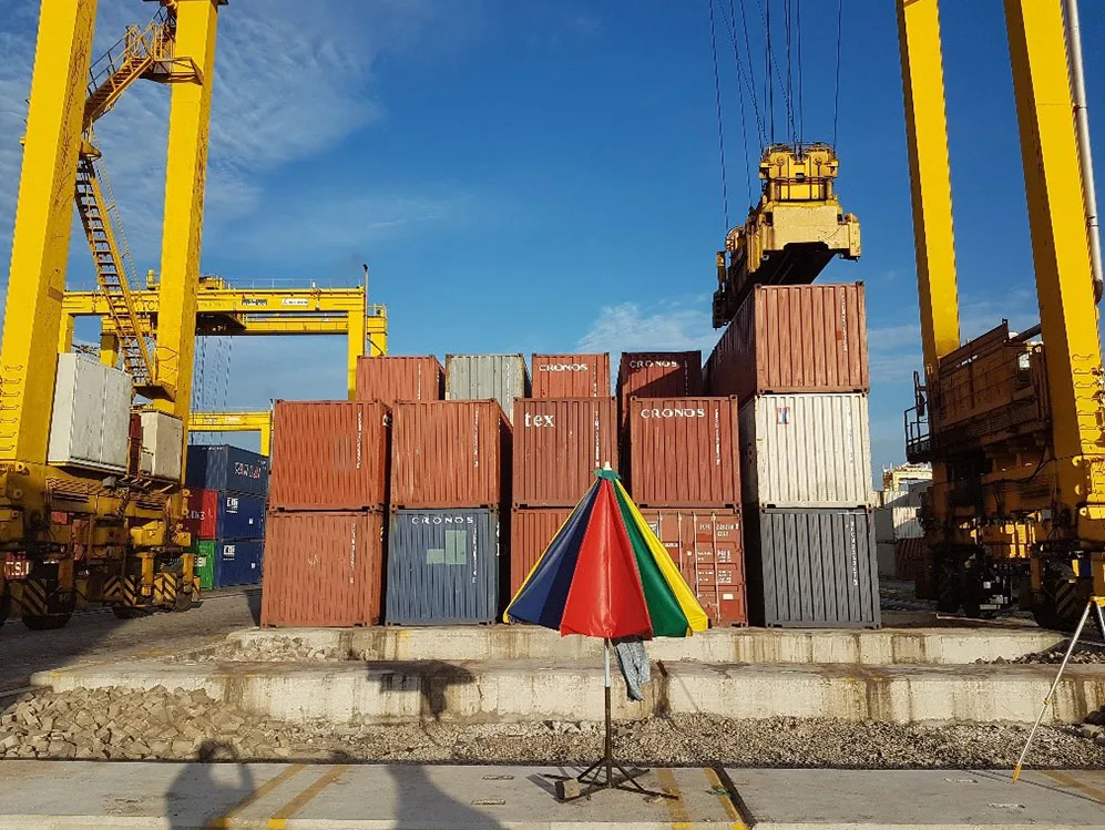
Railway Track Load Test
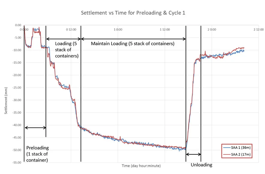
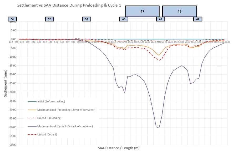
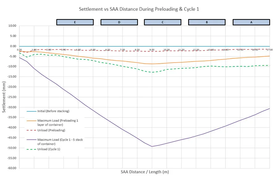
Settlement Monitoring for Stacking Load Test in Container Port
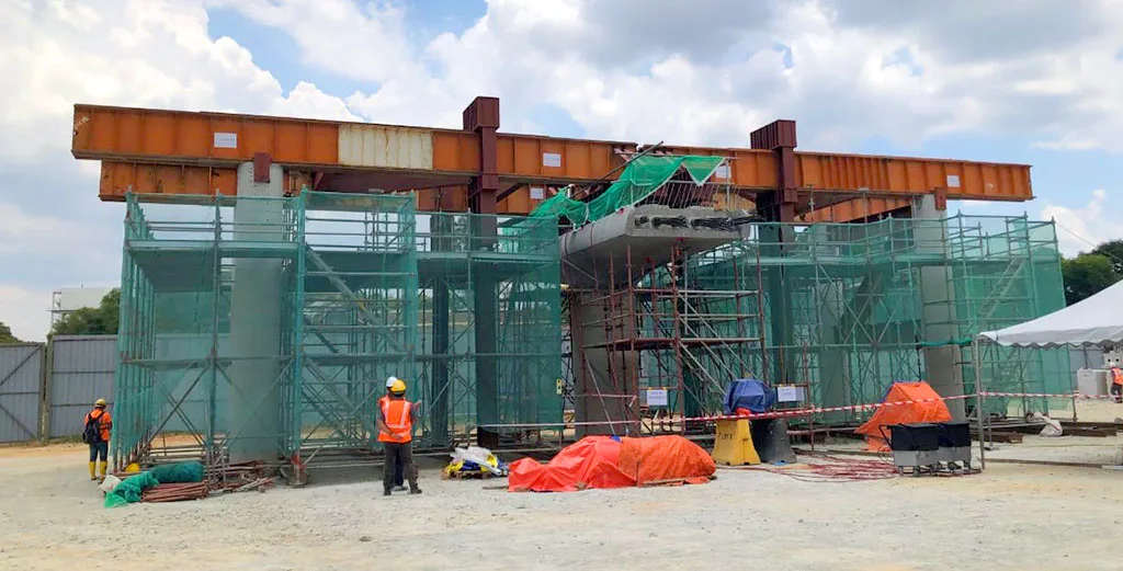
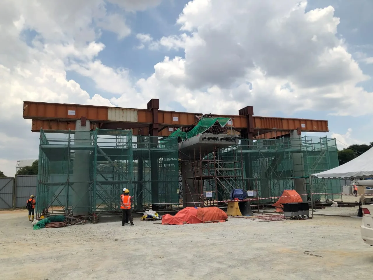
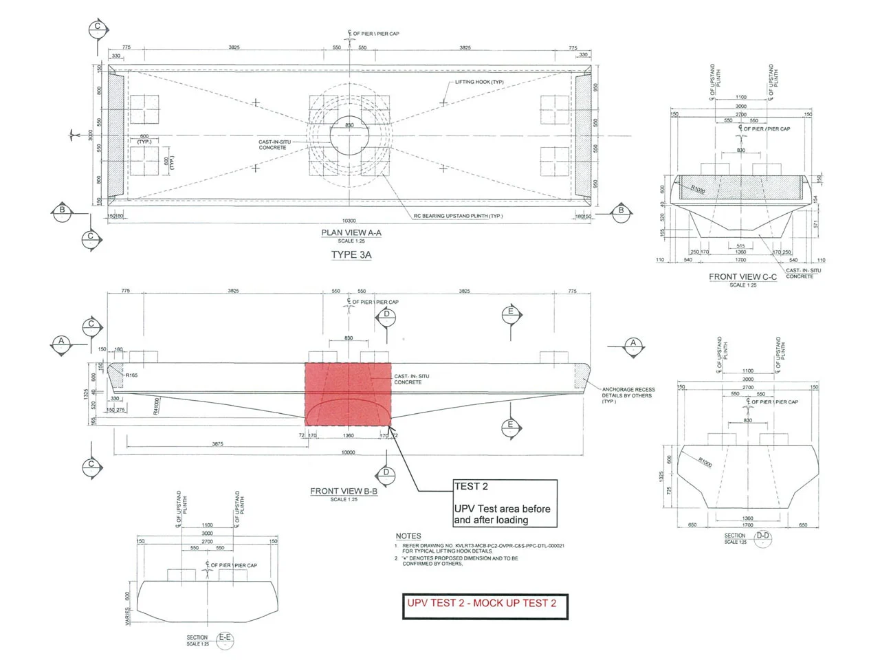
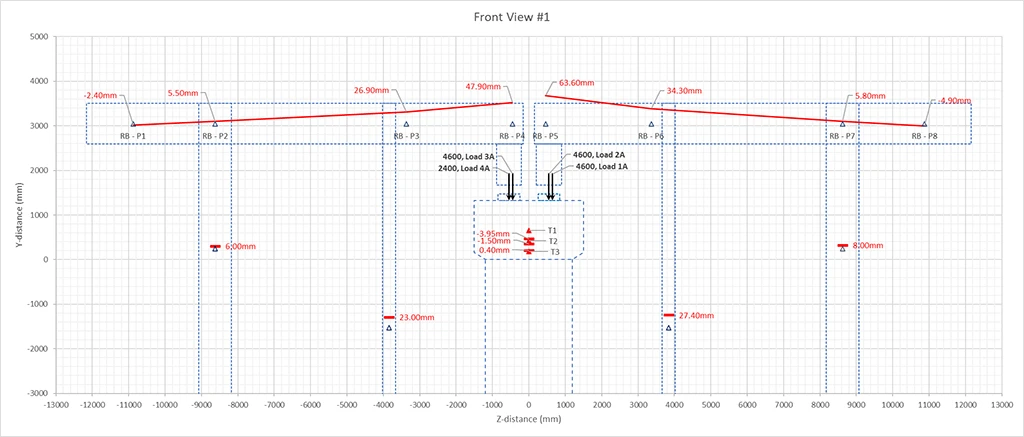
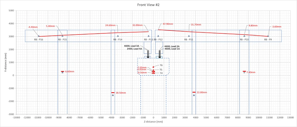
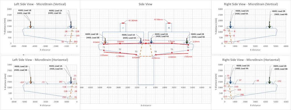
Pilot Test on Launching of Prefabricated Concrete Girder
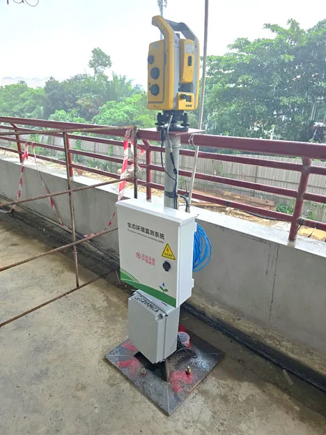
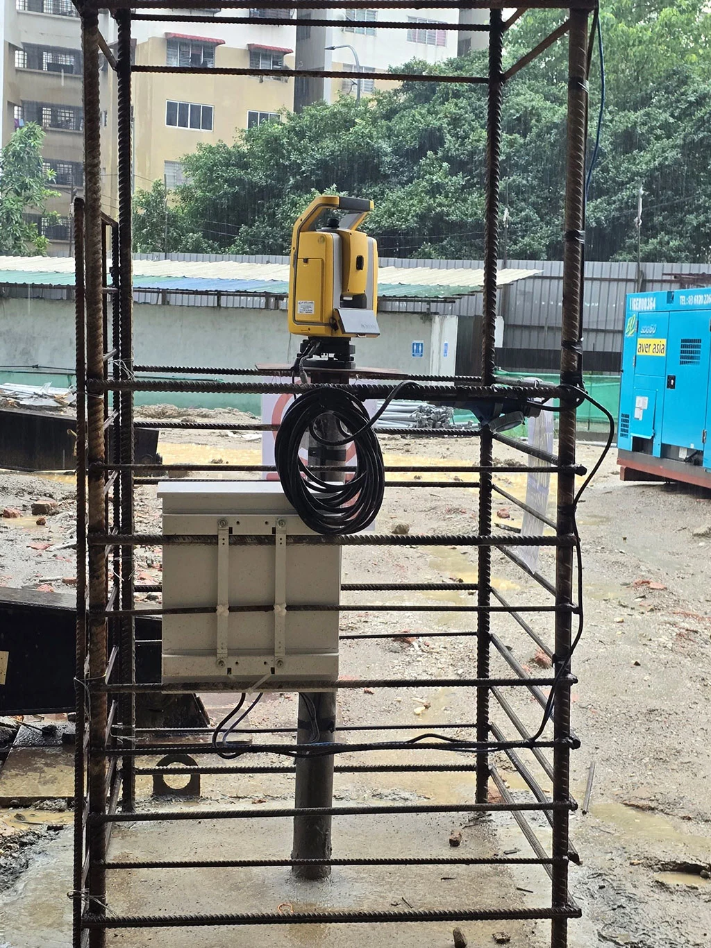
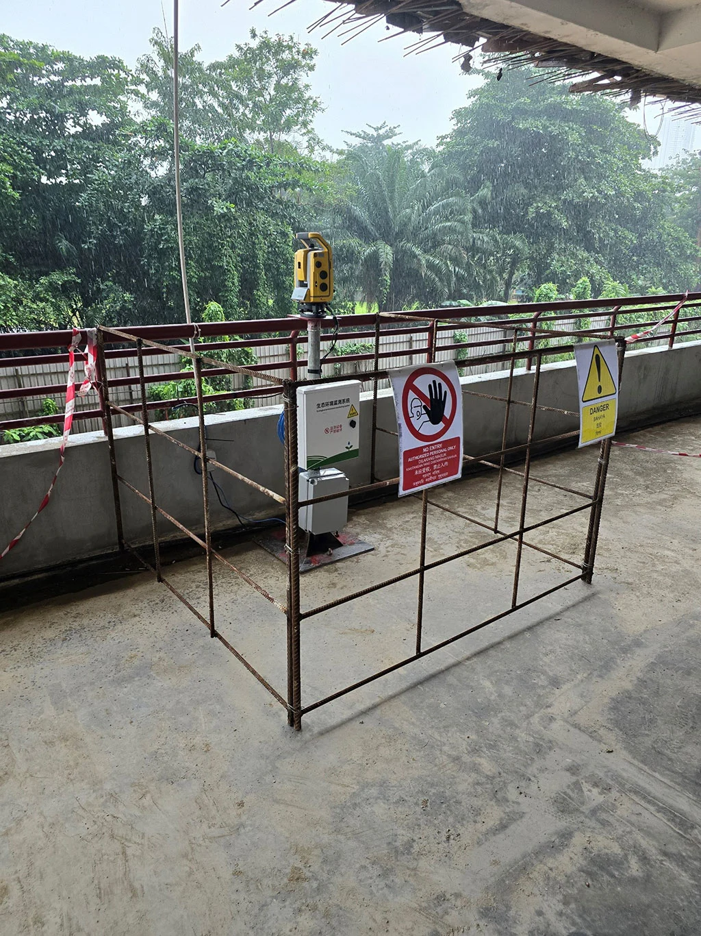
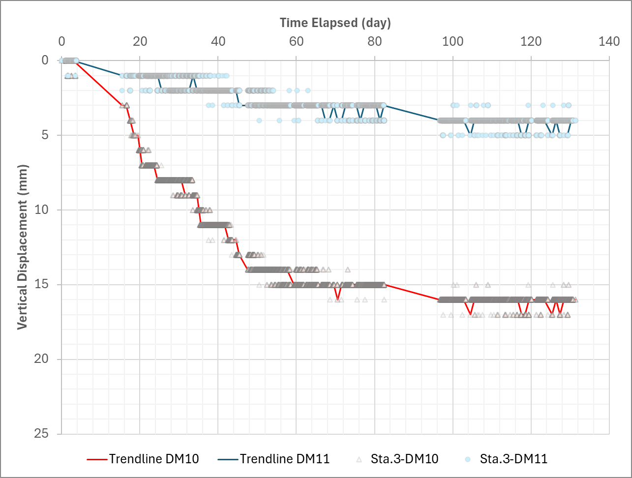
Automatic & Real-Time Monitoring of Structures
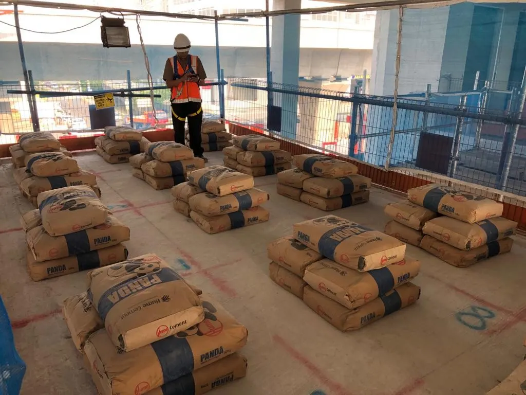
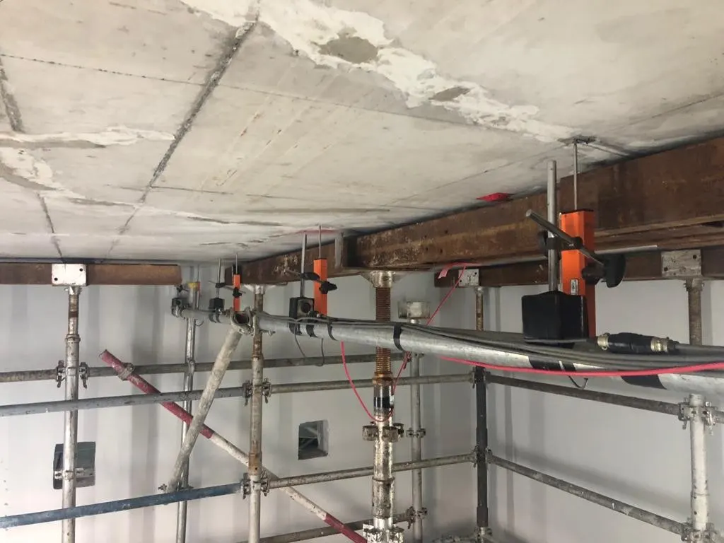
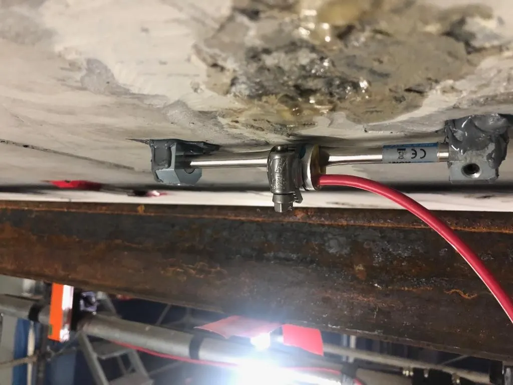
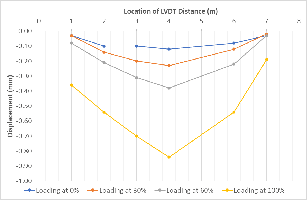
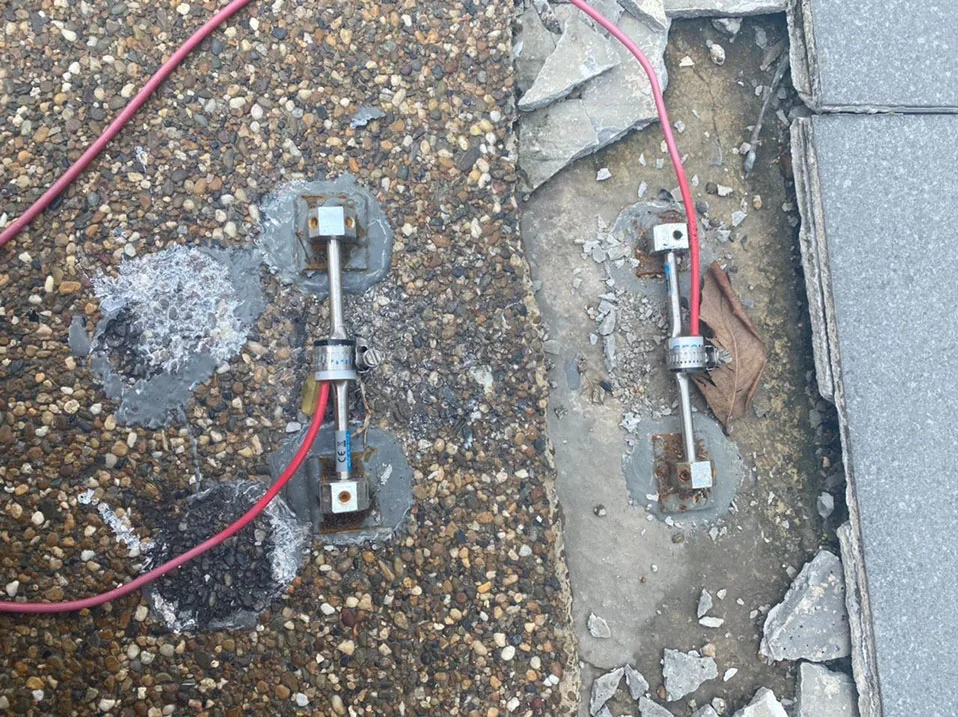
Static Load Test on Concrete Slab
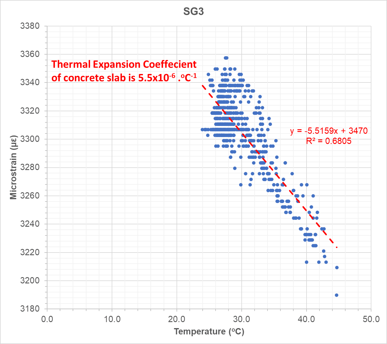
Thermal Expansion and Strain Monitoring on Concrete Slab